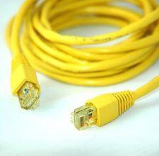
A Cisco console cable is used to connect a computer system directly into a networking device, such as a switch or a router. The cable consists of a DB9 (female) connector on one end and a RJ45 (male) connector on the other. A DB9 connector looks similar to a typical monitor cable and a RJ45 looks like an ethernet cable.
- DB9 connector
- DB9 housing
- Cat5e straight-through cable with RJ45 connectors
- Soldering iron
- Wire strippers
- Magnifying glass (optional)
Identifying the Wires
1. View the RJ45 connector of the Cat5e cable under the magnifying glass.
2. Identify and record what color wires are attached to which ports. Looking at the connector with the clip facing up, port 1 is on the right and port 8 is on the left.
If the wire on port 1 (the furthest right) is white-orange, then the wiring sequence is as follows: 1 – white-orange, 2 – orange, 3 – white-green, 4 – blue, 5 – white-blue, 6 – green, 7 – white-brown, 8 – brown.
If the wire on port 1 is white-green, however, the wiring sequence is as follows: 1 – white-green, 2 – green, 3 – white-orange, 4 – blue, 5 – white-blue, 6 – orange, 7 – white-brown, 8 – brown.
3. Cut one end of the Cat5e cable off, then pull back the shielding (the outer coat of the cable) to reveal the inner wires.
4. Separate and strip the wires.
Attaching the DB9 Connector
1. Slide the DB9 housing onto the Cat5e cable so that the stripped wires come out the wide part of the housing.
2. View the DB9 connector with the exposed points facing the user and the wider part of the connector facing up.
3. Make note of the point numbers.
From the top row, starting at the left, the points are numbered 1 through 5. The bottom row is numbered 6 through 9, with 6 being on the leftmost point.
4. Solder the stripped wires from the Cat5e cable to the DB9 connector.
Where “port” refers to the RJ45 connector and “point” refers to the DB9 connector, connect the wires in the following order: Port 1 to Point 8, Port 2 to Point 6, Port 3 to Point 2, Port 4 to Point 5, Port 5 to Point 5, Port 6 to Point 3, Port 7 to Point 4, and Port 8 to Point 7.
Points 1 and 9 are not used. Use the color key from Step 2 to identify which color wire is connector to which port.
5. Slide the DB9 housing up and seal it to the connector.

No comments:
Post a Comment